CubeSTEP Payload Hardware and Firmware
Academic Research Project, 2022-2023
The CubeSat Technology Exploration Program (CubeSTEP) is a joint collaboration between Cal Poly Pomona (CPP) and NASA’s Jet Propulsion Laboratory (JPL). The program recently received $900,000 in funding from NASA to carry out its mission(link). Our project was presented to the AIAA Science and Technology Forum and Exposition(link). I worked on the program during my ‘22-‘23 school year at CPP.

Mission Statement
- Develop a generic, yet fully-featured, CubeSat platform that future CPP projects can use as a foundation to advance their research.
- Utilize additive manufacturing to allow for custom payloads with minimal modifications to the platform.
- Develop and test an Oscillating Heat Pipe (OHP) integrated battery case which was provided by JPL.
Objective
The satellite had multiple computer systems that needed to be developed and integrated into the on-board computer (OBC) and the flight software.
- Attitude Determination and Control System (ACS)
- UHF Antenna and Transmitter
- Electrical Power System (EPS)
- Payload Processor
My primary assignment had two aspects: to develop the Payload processor (ESP32-Pico-D4) and model its required functionality in the flight software (JPL’s F-Prime) to allow the OBC to interface with the payload.
This page will cover my experience developing the firmware for the ESP32 processor. See CubeSTEP Flight Software(link) for commentary on F-Prime development.
Per the requirements, the payload processor needed to be able to record temperatures from the payload’s 16 thermistors, send a 5V PWM signal to power the payload’s heating element, and interact with the main computer over I2C. I was also given Espressif’s ESP32-Pico-D4 to accomplish those requirements. The ESP32 is a microcontroller family from Espressif that is built around dual 32-bit Xtensa microprocessors. It is functionally similar to the more-popuar STM32 microcontroller family and ARM’s Cortex-M microprocessors.
Espressif’s development tool, called ESP-IDF, has an official VS Code extention that I used to debug and build the firmware. All of the firmware’s application code and hardware drivers were written by myself and directly on top of Espressif’s provided APIs. I wanted to challenge myself to not depend on third-party libraries or online example code. Of course, I did reference many online resources and open-source repositories to learn concepts like I2C and FreeRTOS, but I tried to force myself to rely on the ESP32 and ESP-IDF’s user guides as much as possible. Because of this, I am very proud of how lean and purpose-oriented the resulting code is. The project’s repository can be viewed on GitHub(link).
The Firmware
FreeRTOS handles the execution of the required functionality. Only three tasks were needed to cover everything: A task to handle I2C communication and execute commands received from the main computer, an experiment task to manage the PWM signal, and a logging task to record temperatures. Thanks to the ESP32 having a dual-core processor, the I2C task gets its own core while the experiment and logging tasks share the other core.
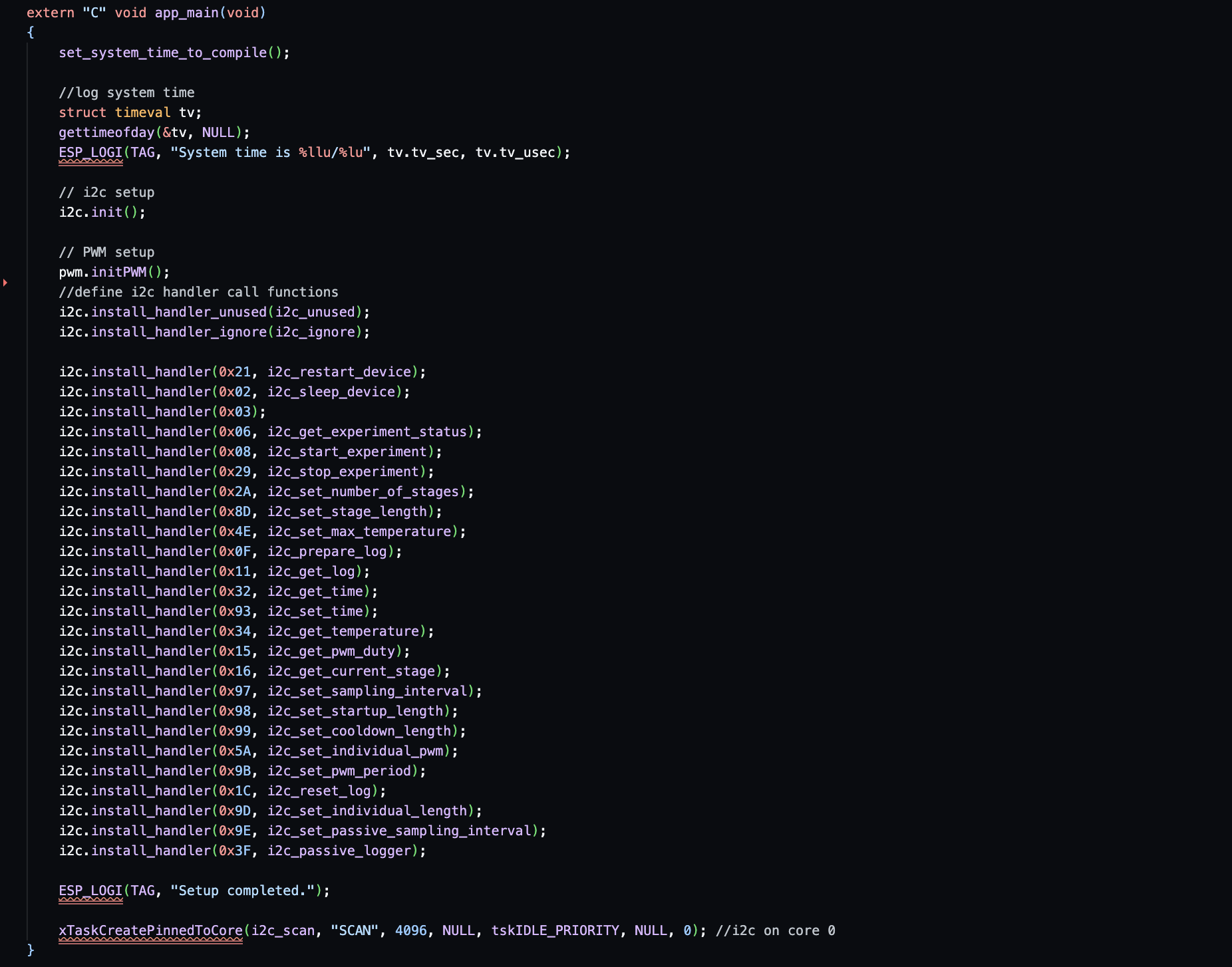
The I2C task is very simple. It repeatedly calls a function from my I2C class to check the I2C buffer for incoming messages. If an incoming message is received, it will parse out an opcode that would be embedded in the first couple bits of the message and compare it to a list of defined opcodes. A unique feature of my I2C implementation is that opcodes can be added to a list within the object along with a pointer to a function once it has been instantiated. So if the opcode received over I2C is recognized, the object can directly call its corresponding function to finish the transaction. I tried to simplify the development process of altering the opcodes (and how they are executed) so that it is accessible to future CubeSTEP researchers who may not be familiar with C++ or even coding in general. If I were to implement this class today, I would do it in a more conventional way, but I was happy to take this opportunity to get more comfortable with pointers and type definitions.
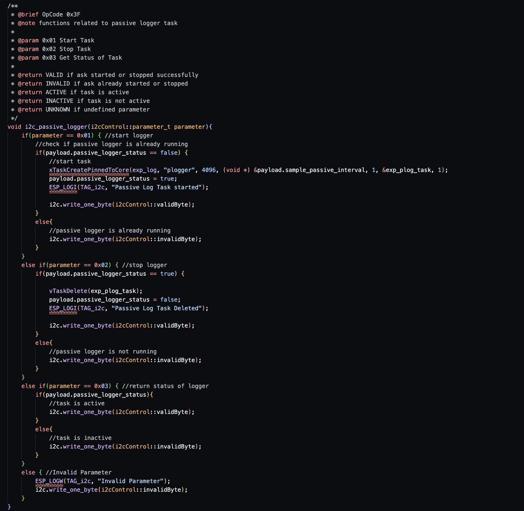
Unlike the I2C task which is always running, the other two tasks run when their opcode is received over I2C. The experiment task uses two hardware timers to generate a PWM signal that ramps from a duty cycle of 0% to 100% over a period of time. The PWM signal goes to a solid state relay that supplies 5V to a heating element in the satellite’s payload. The logging task reads from the 16 thermistors that are attached to the payload and records the temperatues, along with some relevent system telemetry, to SPI flash. A logging task is automatically created with the experiment task and gets deleted when the experiment is completed. A secondary logging task can also be started to passively log temperatures when an experiment is not active as well.
All of the parameters of the experiment and logging task, such as experiment length and logging frequently, are variables and can be set via I2C. This allows the experiment to evolve as our testing team assesses how to best test the payload without ever needing to turn off the satellite.
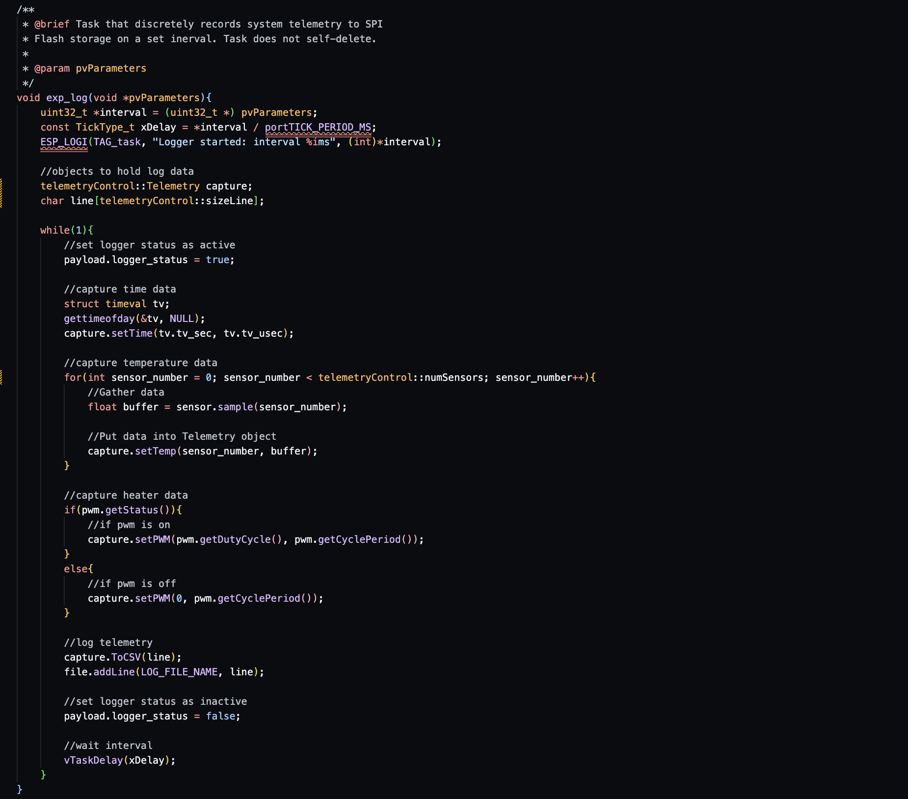
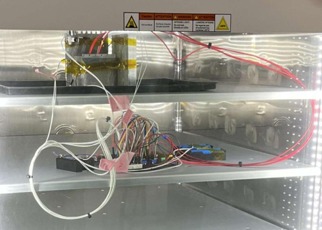
How I tested it
I used a Raspberry Pi 3 to simulate the satellite’s main computer as the i2c master. I created a few C++ scripts using the wiringPi library to model all the i2c behavior that the slave should expect from the main computer. Fuctionally, the scripts can package an opcode and parameter, send it over i2c to the device, and receive messages from the device per the communications protocol I developed.

The Hardware
Using Altium Designer, I created a schematic that combined the ESP32’s devkit board and the added electronics for the thermistors and 5V PWM output.
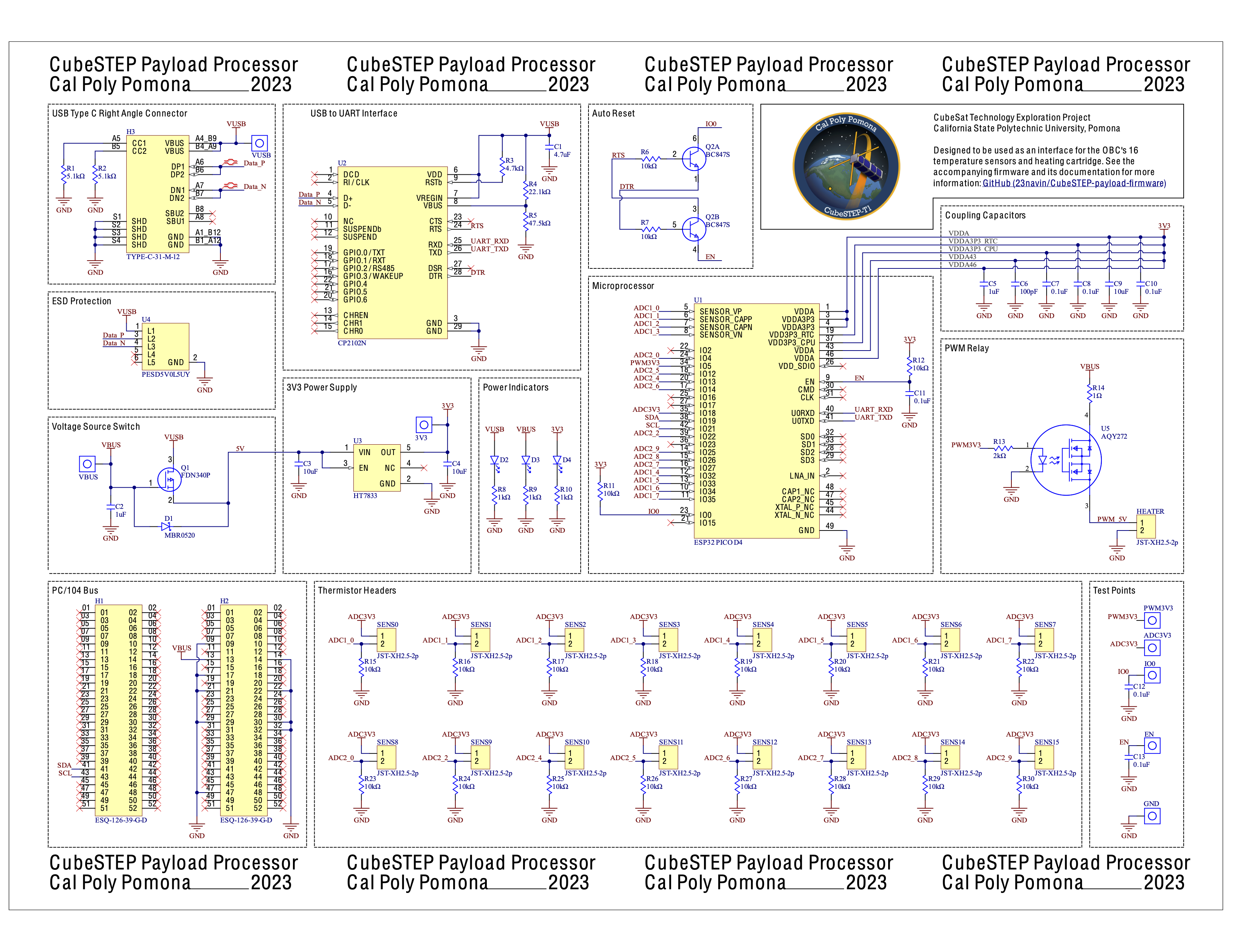
Note: Images on this website get compressed which makes this schematic hard to read. If you want to see it as a PDF, its also on GitHub(link).
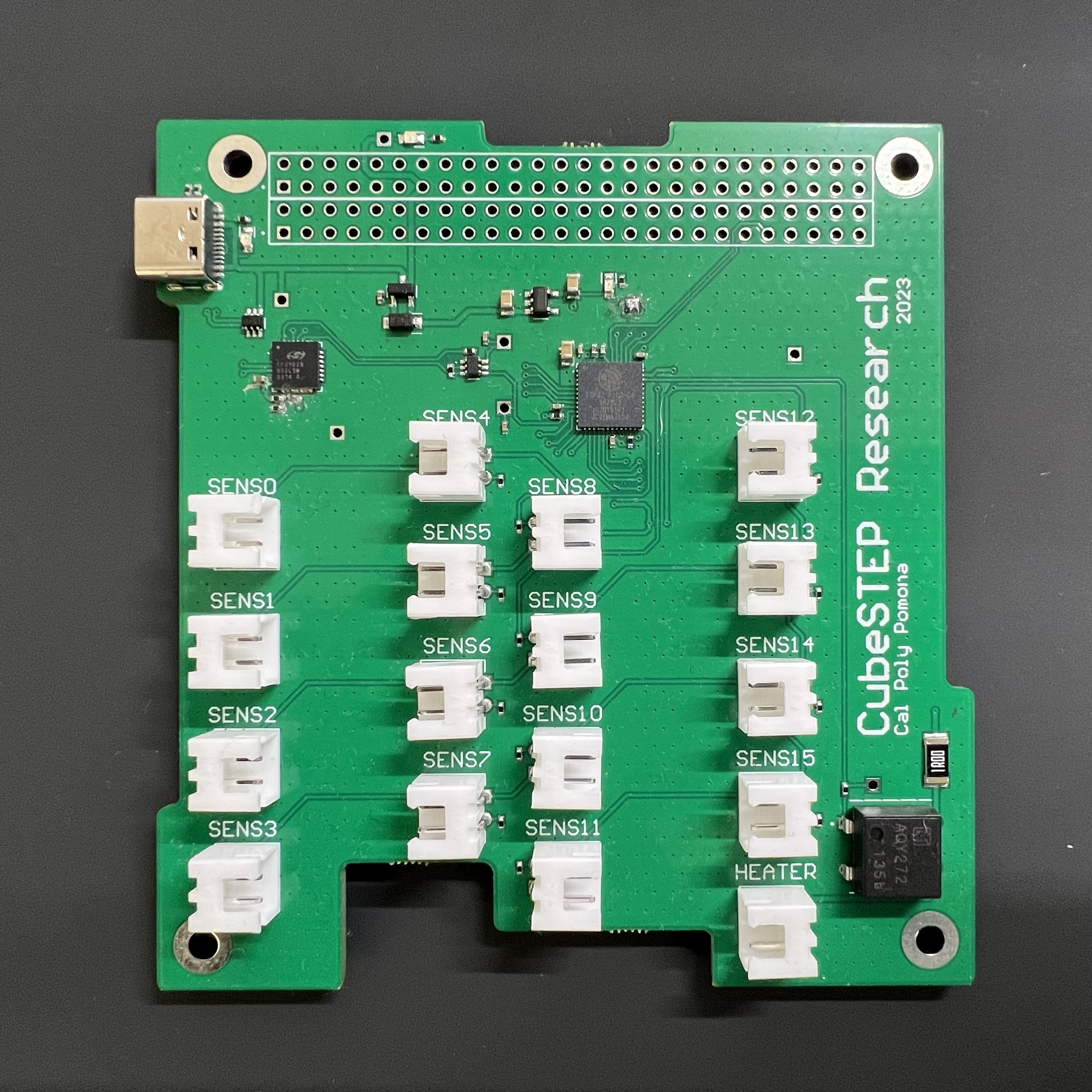
The satellite is built on the PC/104-Plus spec which has requirements for the PCB’s outline, mounting holes, and bus connector. This was my first time designing a PCB so I am sure that it could be done better. I’d definitely want to revisit this project in the future to see if there are any glaring mistakes.
